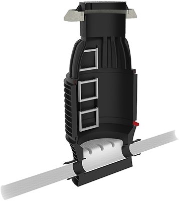
ROMOLD DN1000 Manhole Chamber Product Specifications
The ROMOLD DNI000 Manhole Chamber is designed to be a very simple product to install, and to specify!
The assembly has sufficient variation to cover the needs of any project. ROMOLD DN1000 Manhole Chambers are suitable for Class D 400 applications, installation depths up to 6m, up to 5m of ground water, and can be adjusted in height to the nearest 10mm.
Key details to determine for specification of the chamber are:
- Pipe diameter at outlet
- Pipe entry angle(s)
- Depth to invert of pipe
With this information a simple process can be followed to specify the product.
Load Distribution Ring
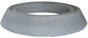
Load Distribution Ring
Part #
CONCRETE RING AML 01
The Load Distribution Ring is used to mount the Cover and must always be used for Class D applications.
DN1000 Cone
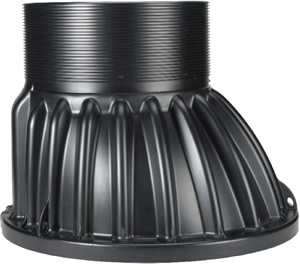
DN1000 Cone Part #
I PP UE 100.63/75 S
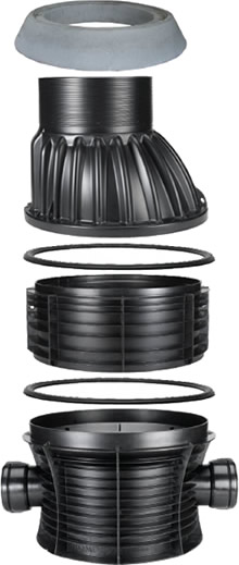
The Cone element is common to any chamber configuration. The height of the Cone is 750mm. This element has a neck diameter of 625mm and is adjustable in height to the nearest 10mmm over a length of 250mm. The Cone has an internal ladder element which aligns with the ladder elements in the Riser Rings.
DN1000 Element Seal
![]()
DN1000 Element Seal Part #
ES 100 IM
Between each chamber element is a common Element Seal. The “Triple Safety Seal” is 100% effective at preventing ingress into the chamber, and egress from the chamber. Two Element Seals are required for a Manhole Chamber with one Riser Ring, and one additional Element Seal is required for each subsequent Riser Ring in the assembly.
DN1000 Riser Rings
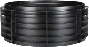
DN1000 Riser Rings Part #
I PP E 100/AA S
| Height of Riser Ring | “AA” |
|---|---|
| 250mm | 25 |
| 500mm | 50 |
| 750mm | 75 |
| 1000mm | 100 |
There are 4 Riser Ring elements which ensure that the exact height of the chamber is achieved. Each Riser Ring has a ladder element to provide safe access to the channel. Riser Rings can be stacked to provide a Manhole assembly with a maximum depth to invert of 6m. Drop pipes can be installed through the wall of the Riser Ring using an ISR seal and CS-I cup saw.
Type and number of Riser Rings will depend on the depth of the manhole.
Example Riser Ring part #
I PP E 100/AA S
Where “AA” is the height of Riser Ring.
DN1000 Base
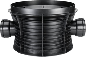
DN1000 Base
There is a wide range of Base options to meet the requirements of almost any project. Each Base element has pipe sockets with integrated rubber ring seals, making for easy connection of plain wall PVC pipe according to AS/NZS 1254 and AS/NZS 1260. Integrated benching in each base provides optimum hydraulic efficiency, whilst saving time during the installation process. The DN1000 Base has a flat bottom allowing for extremely simple levelling. The total height of the base is 690mm. The distance from the bottom of the Base to the pipe invert (for all pipe diameters) is 190mm. This means that the base has an effective height of 500mm from pipe invert.
DN100 Base Specifications
The part number for the Base element is:
I PP B CC 100.DD/50-EEE°
Where:
- "B"
- is the number of inlets (1, 2 or 3)
- "CC"
- defines the channel layout
(Straight, Bent, Multiple Inlet, Opposing Inlets) - "DD"
- defines the pipe size
- "EEE"
- defines the inlet angle in degrees
* for straight channel base options no "EEE" angle is required
| Channel Layout | “CC” |
|---|---|
| Straight | B |
| Bent | BB |
| Multiple Inlet | BL |
| Opposing Inlets | BT |
| Pipe Size | “DD” |
|---|---|
| DN150 | 15 |
| DN175 | 20 |
| DN225 | 25 |
| DN300 | 30 |
| DN375 | 40 |
| Inlet Angle | “EEE” |
|---|---|
| Type BB | |
| 90 degrees | 90 |
| 105 degrees | 105 |
| 120 degrees | 120 |
| 135 degrees | 135 |
| 150 degrees | 150 |
| 165 degrees | 165 |
| Inlet Angle | “EEE” |
|---|---|
| Type BB | |
| 195 degrees | 195 |
| 210 degrees | 210 |
| 225 degrees | 225 |
| 240 degrees | 240 |
| 255 degrees | 255 |
| 270 degrees | 270 |
| Inlet Angle | “EEE” |
|---|---|
| Type BL - 2 Inlet | |
| 180° & 90° | 90 |
| 180° & 270° | 270 |
| Type BL - 3 Inlet | |
| 120°&180°&240° | 60 |
| 90°&180°&270° | 90 |
| Type BT - 2 Inlet | |
| 90° & 270° | 90 |
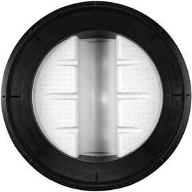
Straight B
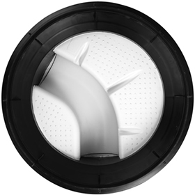
Bent BB
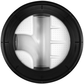
Multiple Inlet 2BL
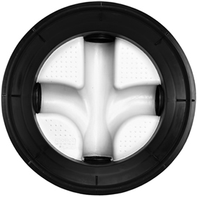
Multiple Inlet 3BL
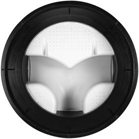
Opposing Inlet 2BT
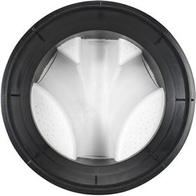
Opposing Inlet 3BL
To help with the correct specification for your requirements the following additional information should be provided:
- Job site location
- Council region
- Maximum height of ground water at install site
- Intended loading class (Class A, B, C or D)
- The Cover required (please see our Product Specification information for Saint-Gobain PAM Covers)
- Any special requirements; such as change of pipe diameter at the chamber, or drop pipes being used.
